Bearings are critical components in gearboxes. Their load-carrying capacity, service life, and reliability directly determine the performance of the entire transmission system. Premature bearing failure can lead to unplanned downtime, increased maintenance costs, and even serious safety incidents. Therefore, accurately analyzing bearing loads, reasonably calculating life, and implementing optimization measures to improve durability are key aspects of gearbox design.
This article systematically covers:
Bearing load analysis (static & dynamic loads)
Bearing life calculation methods (L10 life, modified life)
Common failure modes and improvement measures
Modern simulation and condition monitoring techniques
01 Gearbox Bearing Load Analysis
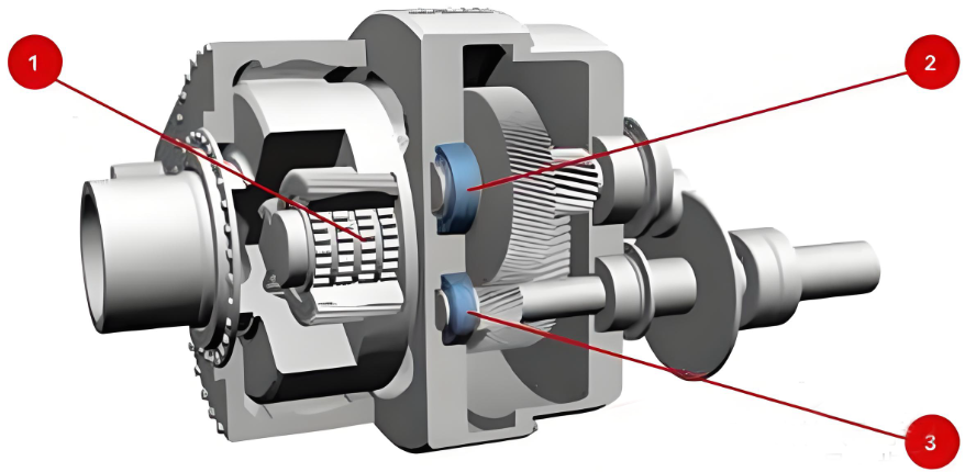
1.1 Basic Bearing Loads
Bearings in gearboxes are mainly subjected to the following loads:
Radial load (Fr): Caused by gear meshing forces, shaft self-weight, belt/chain tension, etc.
Axial load (Fa): Thrust forces generated by helical gears, bevel gears, or worm drives.
Moment load (M): Resulting from gear misalignment, shaft deflection, etc.
Fatigue limit of material (significant life extension when Pu/P ≤ 0.05)
2.3 Finite Element Assisted Life Prediction
Modern CAE tools (ANSYS, Romax, SKF Bearing Tool) enable:
Contact stress field analysis
Fatigue life prediction based on Miner’s cumulative damage rule
Import of realistic load spectra for higher accuracy
03 Common Failure Modes and Improvement Measures in Gearbox Bearings
3.1 Main Failure Modes
(Early failure leads to downtime, high repair costs, and safety risks — specific modes not exhaustively listed but implied: fatigue, wear, overheating, etc.)